


Fire Resisting Cable |
||||||||||
![]() Fire Resisting Cables
Fire Resisting Cables
600/1000V Mica+LSZH Insulated, Non-sheathed Power Cables to BS EN 50525-3-41 (Single Core)
FFX100 1mZ-R (CU/MGT+LSZH 600/1000V Class 2)
APPLICATION
The cables are mainly used in power stations, mass transit underground passenger systems, airports,
petrochemical plants, hotels, hospitals and high-rise buildings.
STANDARDS
Basic design adapted from BS EN 50525-3-41
FIRE PERFORMANCE
Circuit Integrity |
IEC 60331-21; BS 6387; BS 8491 |
Flame Retardance (Single vertical wire or cable test) |
IEC 60332-1-2; EN 60332-1-2 |
Halogen free |
IEC 60754-1; EN 50267-2-1 |
No Corrosive Gas Emission |
IEC60754-2; EN 50267-2-2 |
Minimum Smoke Emission |
IEC 61034-2; EN 61034-2 |
VOLTAGE RATING
600/1000V
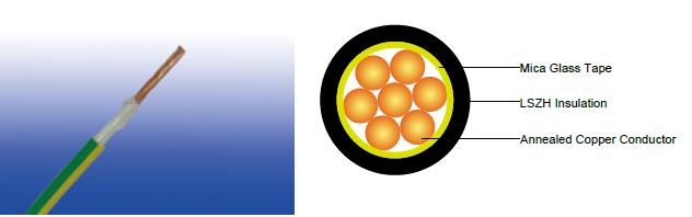
CABLE CONSTRUCTION
Conductor : Annealed copper conductor, stranded according to BS EN 60228 class 2.
Fire Barrier : Mica glass tape.
Insulation : Crosslinked polyolefin material type EI 5 according to EN 50363-5.
Outer Sheath Option : UV resistance, hydrocarbon resistance, oil resistance, anti-rodent and anti-termite
properties can be offered as option.
COLOUR CODE
Black, Blue, Brown, Grey, Orange, Pink, Red, Turquoise, Violet, White, Green and Yellow. Bi-colours of any
combination of the above mono-colours are permitted.
PHYSICAL AND THERMAL PROPERTIES
Maximum temperature range during operation : 90°C
Maximum short circuit temperature (5 Seconds) : 250°C
Minimum bending radius :
OD<8mm : 4 × Overall Diameter
8mm≤OD≤12mm : 5 × Overall Diameter
OD>12mm : 6 × Overall Diameter
CONSTRUCTION PARAMETERS
Conductor |
FFX100 1mZ-R |
|||
No. of Cores × Cross-sectional Area |
Conductor Class |
Nominal Insulation Thickness |
Nominal Overall Diameter |
Approx. Weight |
No.×mm² |
|
mm |
mm |
kg/km |
1x1.5 |
2 |
0.7 |
4.1 |
27 |
1x2.5 |
2 |
0.8 |
4.7 |
39 |
1x4.0 |
2 |
0.8 |
5.3 |
57 |
1x6.0 |
2 |
0.8 |
5.8 |
78 |
1x10 |
2 |
1.0 |
7.2 |
125 |
1x16 |
2 |
1.0 |
8.2 |
186 |
1x25 |
2 |
1.2 |
10.0 |
291 |
1x35 |
2 |
1.2 |
11.2 |
382 |
1x50 |
2 |
1.4 |
13.0 |
517 |
1x70 |
2 |
1.4 |
15.0 |
728 |
1x95 |
2 |
1.6 |
17.0 |
1003 |
1x120 |
2 |
1.6 |
19.0 |
1239 |
1x150 |
2 |
1.8 |
21.0 |
1529 |
1x185 |
2 |
2.0 |
23.0 |
1910 |
1x240 |
2 |
2.2 |
26.0 |
2492 |
1x300 |
2 |
2.4 |
29.0 |
3113 |
1x400 |
2 |
2.6 |
32.5 |
3964 |
1x500 |
2 |
2.8 |
36.0 |
4965 |
1x630 |
2 |
2.8 |
40.0 |
6376 |
ELECTRICAL PROPERTIES
Conductor operating temperature : 90°C
Ambient temperature : 30°C
Current-Carrying Capacities (Amp) according to BS 7671:2008 table 4E1A
Conductor cross-sectional area |
Ref. Method A (enclosed in conduit in thermally insulating wall etc.) |
Ref. Method B (enclosed in conduit on a wall or in trunking etc.) |
Ref. Method C (clipped direct) |
Ref. Method F (in free air or on a perforated cable tray, horizontal or vertical etc) |
Ref. Method G (in free air) |
||||||
Touching |
Spaced by one cable diameter |
||||||||||
2 cables, single-phase a.c. or d.c. |
3 or 4 cables, three-phase a.c. |
2 cables, single-phase a.c. or d.c |
3 or 4 cables, three-phase a.c. |
2 cables, single-phase a.c. or d.c. flat and touching |
3 or 4 cables, three-phase a.c. flat and touching or trefoil |
2 cables, single-phase a.c. or d.c. flat |
3 cables, three-phase a.c. flat |
3 cables, three-phase a.c. trefoil |
2 cables, single-phase a.c. or d.c. or 3 cables three-phase a.c. flat |
||
Horizontal |
Vertical |
||||||||||
1 |
2 |
3 |
4 |
5 |
6 |
7 |
8 |
9 |
10 |
11 |
12 |
mm² |
A |
A |
A |
A |
A |
A |
A |
A |
A |
A |
A |
1.5 |
19 |
17 |
23 |
20 |
25 |
23 |
- |
- |
- |
- |
- |
2.5 |
26 |
23 |
31 |
28 |
34 |
31 |
- |
- |
- |
- |
- |
4.0 |
35 |
31 |
42 |
37 |
46 |
41 |
- |
- |
- |
- |
- |
6.0 |
45 |
40 |
54 |
48 |
59 |
54 |
- |
- |
- |
- |
- |
10 |
61 |
54 |
75 |
66 |
81 |
74 |
- |
- |
- |
- |
- |
16 |
81 |
73 |
100 |
88 |
109 |
99 |
- |
- |
- |
- |
- |
25 |
106 |
95 |
133 |
117 |
143 |
130 |
161 |
141 |
135 |
182 |
161 |
35 |
131 |
117 |
164 |
144 |
176 |
161 |
200 |
176 |
169 |
226 |
201 |
50 |
158 |
141 |
198 |
175 |
228 |
209 |
242 |
216 |
207 |
275 |
246 |
70 |
200 |
179 |
253 |
222 |
293 |
268 |
310 |
279 |
268 |
353 |
318 |
95 |
241 |
216 |
306 |
269 |
355 |
326 |
377 |
342 |
328 |
430 |
389 |
120 |
278 |
249 |
354 |
312 |
413 |
379 |
437 |
400 |
383 |
500 |
454 |
150 |
318 |
285 |
393 |
342 |
476 |
436 |
504 |
464 |
444 |
577 |
527 |
185 |
362 |
324 |
449 |
384 |
545 |
500 |
575 |
533 |
510 |
661 |
605 |
240 |
424 |
380 |
528 |
450 |
644 |
590 |
679 |
634 |
607 |
781 |
719 |
300 |
486 |
435 |
603 |
514 |
743 |
681 |
783 |
736 |
703 |
902 |
833 |
400 |
- |
- |
683 |
584 |
868 |
793 |
940 |
868 |
823 |
1085 |
1008 |
500 |
- |
- |
783 |
666 |
990 |
904 |
1083 |
998 |
946 |
1253 |
1169 |
630 |
- |
- |
900 |
764 |
1130 |
1033 |
1254 |
1151 |
1088 |
1454 |
1362 |
Voltage Drop (Per Amp Per Meter) according to BS 7671:2008 table 4E1B
Conductor cross-sectional area |
2 cables d.c. |
2 cables, single-phase a.c. |
3 or 4 cables, three-phase a.c. |
|||||||||||||||||||
Ref. Methods A&B (enclosed in conduit or trunking) |
Ref. Methods C & F(clipped direct, on trays or in free air) |
Ref. Methods A & B (enclosed in conduit or trunking) |
Ref. Methods C & F (clipped direct, on trays or in free air) |
|||||||||||||||||||
Cables touching |
Cables spaced* |
Cables touching, Trefoil |
Cables touching, Flat |
Cables spaced*, Flat |
||||||||||||||||||
1 |
2 |
3 |
4 |
5 |
6 |
7 |
8 |
9 |
||||||||||||||
mm² |
mV/A/m |
mV/A/m |
mV/A/m |
mV/A/m |
mV/A/m |
mV/A/m |
mV/A/m |
|||||||||||||||
1.5 |
31 |
31 |
31 |
31 |
27 |
27 |
27 |
27 |
||||||||||||||
2.5 |
19 |
19 |
19 |
19 |
16 |
16 |
16 |
16 |
||||||||||||||
4.0 |
12 |
12 |
12 |
12 |
10 |
10 |
10 |
10 |
||||||||||||||
6.0 |
7.9 |
7.9 |
7.9 |
7.9 |
6.8 |
6.8 |
6.8 |
6.8 |
||||||||||||||
10 |
4.7 |
4.7 |
4.7 |
4.7 |
4.0 |
4.0 |
4.0 |
4.0 |
||||||||||||||
16 |
2.9 |
2.9 |
2.9 |
2.9 |
2.5 |
2.5 |
2.5 |
2.5 |
||||||||||||||
r |
x |
z |
r |
x |
z |
r |
x |
z |
r |
x |
z |
r |
x |
z |
r |
x |
z |
r |
x |
z |
||
25 |
1.85 |
1.85 |
0.31 |
1.90 |
1.85 |
0.190 |
1.85 |
1.85 |
0.28 |
1.85 |
1.60 |
0.27 |
1.65 |
1.60 |
0.165 |
1.60 |
1.60 |
0.190 |
1.60 |
1.60 |
0.27 |
1.65 |
35 |
1.35 |
1.35 |
0.29 |
1.35 |
1.35 |
0.180 |
1.35 |
1.35 |
0.27 |
1.35 |
1.15 |
0.25 |
1.15 |
1.15 |
0.155 |
1.15 |
1.15 |
0.180 |
1.15 |
1.15 |
0.26 |
1.20 |
50 |
0.99 |
1.00 |
0.29 |
1.05 |
0.99 |
0.180 |
1.00 |
0.99 |
0.27 |
1.00 |
0.87 |
0.25 |
0.90 |
0.86 |
0.155 |
0.87 |
0.86 |
0.180 |
0.87 |
0.86 |
0.26 |
0.89 |
70 |
0.68 |
0.70 |
0.28 |
0.75 |
0.68 |
0.175 |
0.71 |
0.68 |
0.26 |
0.73 |
0.60 |
0.24 |
0.65 |
0.59 |
0.150 |
0.61 |
0.59 |
0.175 |
0.62 |
0.59 |
0.25 |
0.65 |
95 |
0.49 |
0.51 |
0.27 |
0.58 |
0.49 |
0.170 |
0.52 |
0.49 |
0.26 |
0.56 |
0.44 |
0.23 |
0.50 |
0.43 |
0.145 |
0.45 |
0.43 |
0.170 |
0.46 |
0.43 |
0.25 |
0.49 |
120 |
0.39 |
0.41 |
0.26 |
0.48 |
0.39 |
0.165 |
0.43 |
0.39 |
0.25 |
0.47 |
0.35 |
0.23 |
0.42 |
0.34 |
0.140 |
0.37 |
0.34 |
0.165 |
0.38 |
0.34 |
0.24 |
0.42 |
150 |
0.32 |
0.33 |
0.26 |
0.43 |
0.32 |
0.165 |
0.36 |
0.32 |
0.25 |
0.41 |
0.29 |
0.23 |
0.37 |
0.28 |
0.140 |
0.31 |
0.28 |
0.165 |
0.32 |
0.28 |
0.24 |
0.37 |
185 |
0.25 |
0.27 |
0.26 |
0.37 |
0.26 |
0.165 |
0.30 |
0.25 |
0.25 |
0.36 |
0.23 |
0.23 |
0.32 |
0.22 |
0.140 |
0.26 |
0.22 |
0.165 |
0.28 |
0.22 |
0.24 |
0.33 |
240 |
0.190 |
0.21 |
0.26 |
0.33 |
0.20 |
0.160 |
0.25 |
0.195 |
0.25 |
0.31 |
0.185 |
0.22 |
0.29 |
0.170 |
0.140 |
0.22 |
0.170 |
0.165 |
0.24 |
0.170 |
0.24 |
0.29 |
300 |
0.155 |
0.175 |
0.25 |
0.31 |
0.160 |
0.160 |
0.22 |
0.155 |
0.25 |
0.29 |
0.150 |
0.22 |
0.27 |
0.140 |
0.140 |
0.195 |
0.135 |
0.160 |
0.21 |
0.135 |
0.24 |
0.27 |
400 |
0.120 |
0.140 |
0.25 |
0.29 |
0.130 |
0.155 |
0.20 |
0.125 |
0.24 |
0.27 |
0.125 |
0.22 |
0.25 |
0.110 |
0.135 |
0.175 |
0.110 |
0.160 |
0.195 |
0.110 |
0.24 |
0.26 |
500 |
0.093 |
0.120 |
0.25 |
0.28 |
0.105 |
0.155 |
0.185 |
0.098 |
0.24 |
0.26 |
0.100 |
0.22 |
0.24 |
0.090 |
0.135 |
0.160 |
0.088 |
0.160 |
0.180 |
0.085 |
0.24 |
0.25 |
630 |
0.072 |
0.100 |
0.25 |
0.27 |
0.086 |
0.155 |
0.175 |
0.078 |
0.24 |
0.25 |
0.088 |
0.21 |
0.23 |
0.074 |
0.135 |
0.150 |
0.071 |
0.160 |
0.170 |
0.068 |
0.23 |
0.24 |
Note: *Spacings larger than one cable diameter will result in a large voltage drop.
r = conductor resistance at operating temperature
x = reactance
z = impedance